
Optronix Optronix
←→ navigate F fullscreen contents

Data centre
design.

Designed to the tap-off in our Whitespace Builder. Density-first, airflow always, sized for where you're heading.
Service pack    Commercial in Confidence
→  to begin    F for fullscreen
Contents

What we'll cover.

    The proposition

    Density first. Airflow always.

    A hall is only as good as its design. We model every rack, busbar run and tap-off before anything is ordered, so the build is right the first time.

    Modelled, not sketched

    Every element placed in 2D and 3D and approved before procurement.

    Sized for the load

    Density drives the design. Cooling and power are matched to the kW you'll actually run.

    Room to grow

    Pathways, power and space sized so the next expansion is an addition, not a rebuild.

    Issued from the model Layout drawings in 2D and 3D, rack elevations, power schedules, containment and cable routes, and the as-builts at the end.
    A hall design, by domain

    What we design.

    PLAN CRAH MDA and ODF 600Cold aisle 1200Hot 900Contained cold aisleBusbar A and B over every rowBasket and fibre raceway Reserved for phase two Door A A SECTION A-A Soffit Containment roof Perforated tiles CRAH Hot aisle Cabinet Cold aisle Cabinet Hot aisle Cabinet Basket and fibre raceway Busbar and tap-off Raised floor and void

    Layout & topology

    The grid the whole hall is set out on, drawn around what the room already has.

    Rack rows & aislesGrid, aisle widths and access modelled around pillars, doors and existing services.
    Day-one vs end-stateThe full grid designed up front, day-one populated, growth reserved.
    Designed toTIA-942
    Model first

    From empty room to modelled hall.

    Every rack, busbar run and tap-off placed before anything is ordered.

    DoorCRAHMDA and ODFReservedfor growth1200 cold900 hot600Busbar A and B
    DoorExisting containment, surveyedRedundant tray, to strip outExisting boardColumns, measured???Shell, columns and services. Nothing set out.
    The room you have The hall we model

    Drag the divider. Same shell, same columns, same door: on the right, 80 cabinets in four rows, two contained cold aisles, and a busbar over every row.

    Layout

    The set-out, to the cabinet.

    Cabinets56
    Density12kW per cabinet
    5rows, up to 12 cabinets each
    2contained cold aisles
    112m²rows and aisles, floor area
    672kWIT load, and the heat to remove
    Air, with containmentContained cold aisles, blanked cabinets and balanced airflow.

    Drag either slider. Illustrative layout, set out from the dimensions drawn: 600 mm cabinets twelve to a row, 1200 mm contained cold aisles, 900 mm hot aisles and 1000 mm clearance at the walls. A real hall is designed around its columns, its doors and the plant it already has.

    Airflow

    Air that goes through the racks, not around them.

    Soffit Roof panels and end doors Recirculation Bypass Hot air returns at ceiling level, to the plant CRAH Hot aisle Cabinet Cold aisle Cabinet Hot aisle Blanking panels close the path through the rack Raised floor Floor void, supply plenum Perforated tiles in the cold aisle

    Air goes around the racks

    With nothing closing the top of the aisle, hot air comes back over the cabinet and mixes with the supply.

    Top of rackRuns hottest. The kit at the top of the cabinet sees the warmest air in the room.
    Supply temperatureHeld low to protect the top of the rack, so the plant works harder than it needs to.
    Bypass airCold air leaves the aisle through gaps, open U space and cable cut-outs without cooling anything.
    CapacityUsable cooling runs out before the floor space does.

    Hot and cold aisle containment designed in from day one: the cheapest efficiency you'll ever buy.

    Designing for density

    Ready for what's coming.

    Lower densityHigher density
    Contained cold aisle Cabinet Cabinet Blanking panels, sealed cut-outs, tiles placed to the load CDU Rear-door heat exchangers Coil on the back of the cabinet Flow and return in the floor void, isolated at the row Direct-to-chip liquid Manifold and quick disconnects CDU Drip tray and leak detection under the row Standard rows High-density zone Power and cooling zoned, not averaged One hall, two design points
    Step 01

    Air, with containment

    Containment, blanking and balanced airflow take conventional densities further than most halls ever push them.

    In the roomRoof panels and end doors on every cold aisle, and a blanking panel in every empty U.
    In the floorPerforated tiles placed to the load, and every cable cut-out sealed.
    PlantThe cooling you already have, used properly.
    Designed nowAisle widths and tile positions, so the airflow is set before the cabinets land.
    How the design runs

    Modelled, reviewed, issued from the model.

    Hover to pause. Click a stage to jump.

    Stage 01

    Survey

    We measure and verify the space so the design starts from reality: structure, services, access and constraints, not a PDF of the floor plan.

    Out of this stageA measured room, with the services and constraints recorded.
    The Whitespace Builder

    Three inputs. Same-day design.

    Room dimensions, target racks and available power are all the Whitespace Builder needs to produce the first modelled hall.

    Room dimensionsShell, columns, doors, ceiling height
    Target racksDay one, and the end state
    Available powerWhat the incomer and the plant can give
    A modelled hall and a budget Layout, containment, power and pathways, with the quantities priced
    Target racksDrag the slider 60
    8hours to a modelled hall and a budget, from three inputs
    2design revisions before order, typical
    £0cost of a layout change at design stage

    Illustrative planning figures. Every engagement is scoped properly before we commit numbers.

    The design pack

    What gets issued.

    Rack elevationExample sheet, drawn from the model. Not a client drawing.1U6U12U18U24U30U36U42UODF, OS2 12f ×2Copper, Cat6A ×2Leaf switch ×2Server, 2U ×8ABEXAMPLECABINET R04-12, FRONT42U, 2000 mmLEGENDFibre, OS2Copper, Cat6ASwitchServerBlanking and managementPDU, A and BCABLE SCHEDULE, EXTRACTREFFROMTOTYPELENGTHA-01R04-12 U42 P01-P12MDA ODF-2 P07-P18OS2 12f LC41 mA-02R04-12 U41 P01-P12MDA ODF-2 P19-P30OS2 12f LC41 mC-11R04-12 U39 P01-P24R04-12 U36 P01-P24Cat6A2 mC-12R04-12 U38 P01-P24R04-12 U35 P01-P24Cat6A2 mP-01Busbar BW-04 TO-12AR04-12 PDU-A32A 1P4 mP-02Busbar BW-05 TO-12BR04-12 PDU-B32A 1P4 mPROJECTExample hallDRAWINGRack elevation, R04-12SOURCEOptronix Whitespace BuilderREVA, for illustration only
    01Layout drawings, 2D and 3DThe hall set out: rows, aisles, containment, plant and the routes between them.
    02Rack elevationsEvery cabinet drawn U by U, with the kit, the patching and the blanking in place.
    03Power schedulesBusbar runs, tap-offs, PDUs and the A and B chain traced from the board to the socket.
    04Containment and cable routesPathway tiers drawn and coordinated with lighting, fire and cooling.
    05Cable schedulesEvery link listed with its type, its route, its length and its labels, ready to order and install to.
    06As-builts in CAD and VisioIssued at the end in the format your team already works in.
    07Asset register and DCIM dataCabinets, positions and the power chain, in a shape the DCIM build can take.
    On site

    From the model to the floor.

    The drawings the installers work from come out of the same model you approved, and the as-builts go back into it at the end.
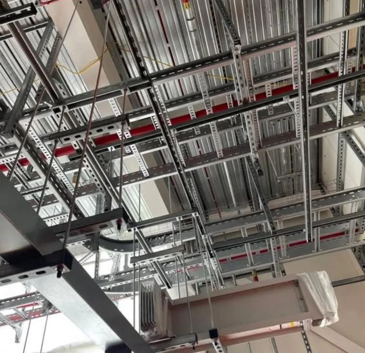
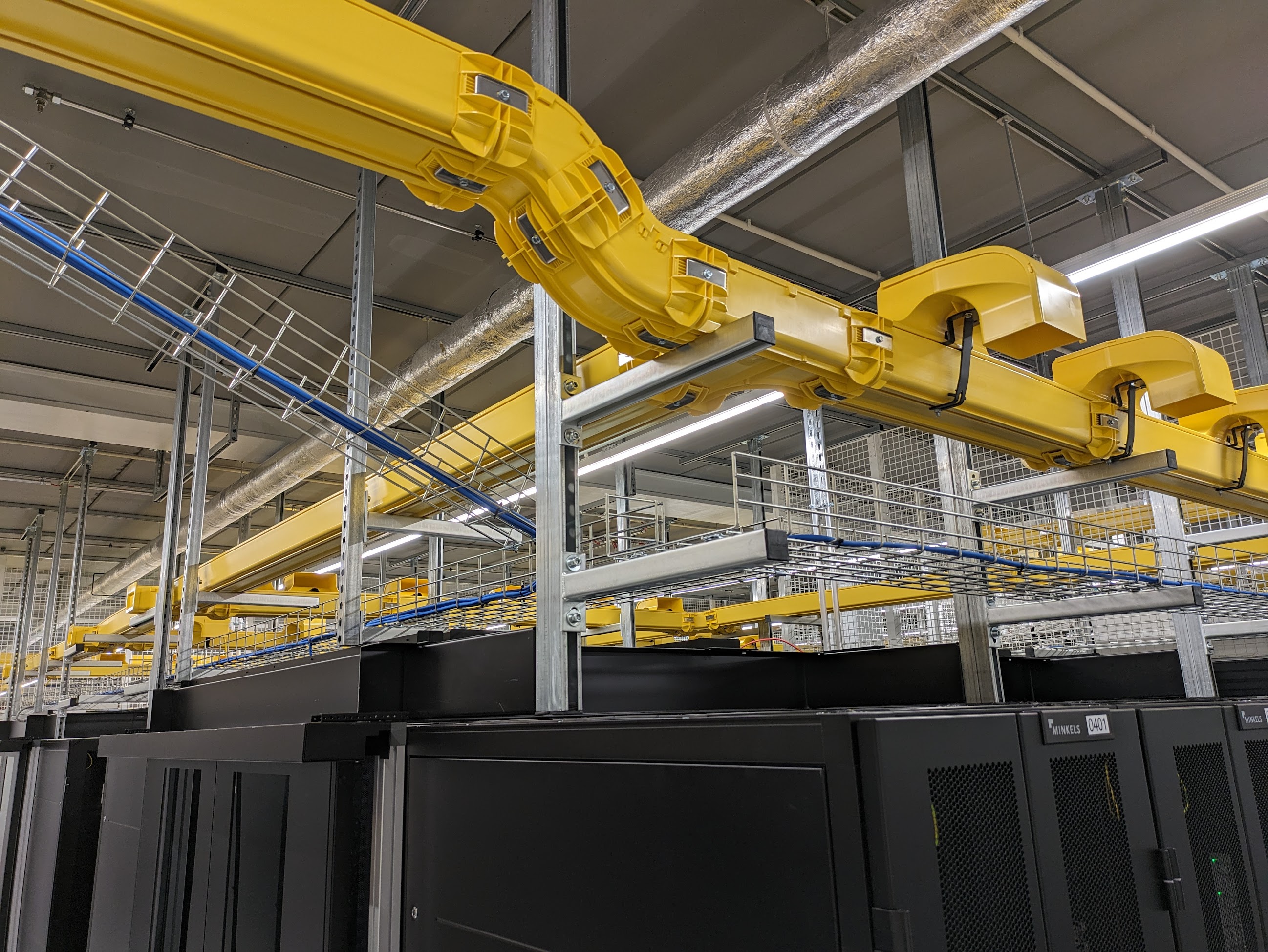
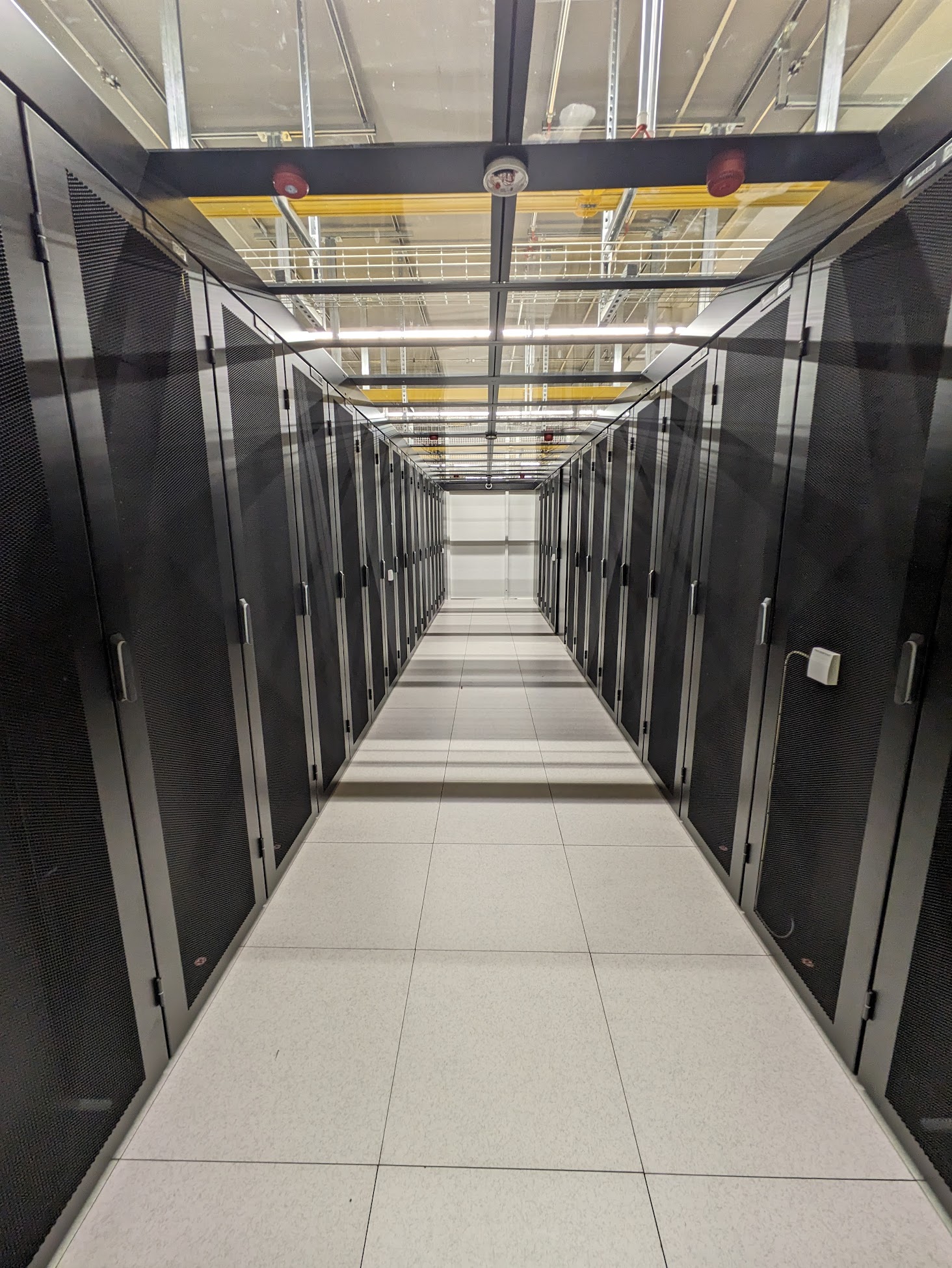
    Aisle containment going in
    Aisle containment going in
    Overhead containment above a row of cabinets
    Overhead containment above a row of cabinets
    The finished aisle
    The finished aisle

    Optronix installations, photographed on site.

    Proof, redacted

    Three phases. One design language.

    EnterprisePhased buildThree years

    An enterprise client grew from one row to a full hall over three phases. Because the end-state was designed on day one, each phase dropped in: no rework, no re-cabling, no surprises.

    24racks in phase one, on a design that already held 96
    96racks at end-state, on the original layout
    0redesigns between phases

    Client identifiers withheld; figures rounded.

    Twelve cabinets to a row, eight rows

    Phase one: 24 cabinets, set out on the end-state grid

    Our engineers

    Where our engineers have worked.

    USAUKEuropeMiddle EastAustralia
    Why Optronix

    Hyperscale design pedigree, any scale.

    Our team has designed halls for some of the largest data centre campuses in the world, where one design scales to hundreds of thousands of links and survives multiple generations. That discipline goes into every project, whatever the size.

    Designed by the people who build it The team drawing the hall is the team that then installs, cables and commissions it. Buildability is checked by the installation team before the pack is issued.
    One model, four disciplines Layout, power, cooling and cabling are drawn together in the same model, not handed between four consultants and reconciled on site.
    Documented to hand over Design packs, rack elevations, cable schedules and as-builts in CAD and Visio, issued in the format your team already works in.
    Related decks

    More detail, deck by deck.

    Next step

    Send us the room.
    We'll model the hall.

    A floor plan, a rack count and the power you have are enough to start. We will come back with a modelled layout, the containment and power design, and the budget that goes with it.

    Data Centre Lifecycle Experts